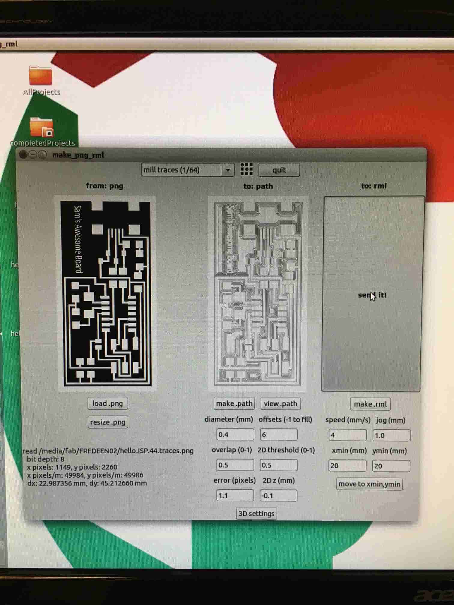
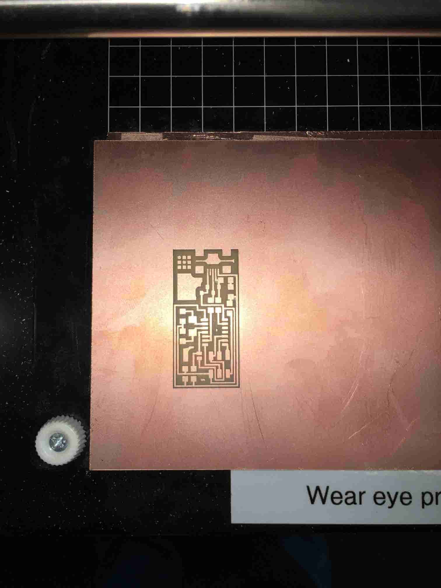
This weeks assignment was to build and program our own isp boards. Since I have not dealt with anything like this before, I wanted a board that had good documentation with it and was an easy build. The board I decided to build was an old fab isp module which can be found here: Fab ISP Board. Using Ubuntu I downloaded the traces.png and outline.png files so that the mill would be able to mill and cut out the board. After the right images had been downloaded I first wanted it to cut out the board itself. Using the program I uploaded the traces.png, shown in Figure 1, and changed the option to the mill traces (1/64) option from the drop down menu. I then changed the offsets to 6 as this would give me a better final cut. Once this was done, I clicked make.path and then make .rml. The mill now had the right stuff for it to mill out the board. I then clicked "send it!" and watched the mill do its work. How exciting! Figure 2 shows the board done after this process.
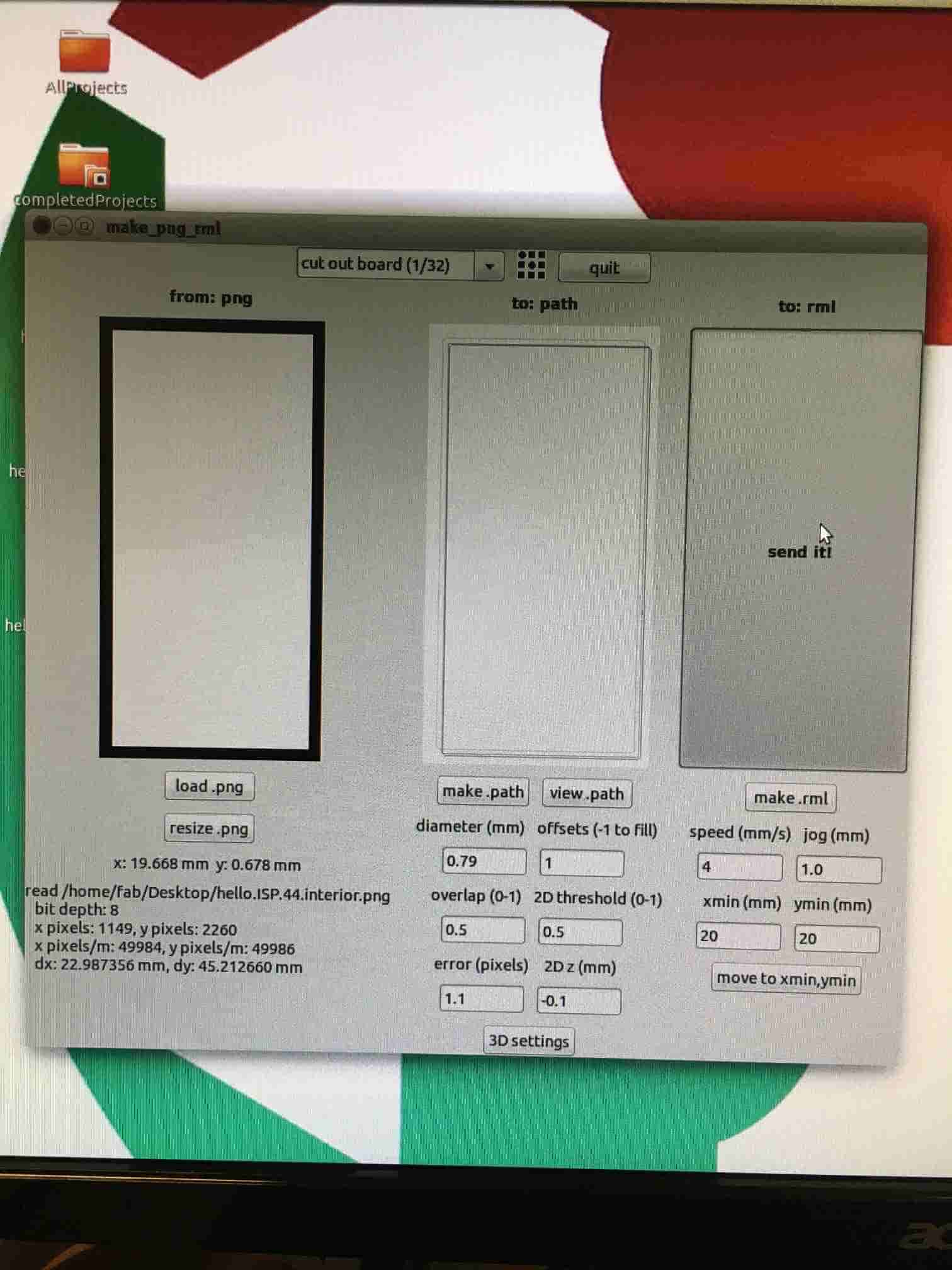
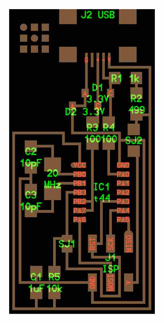
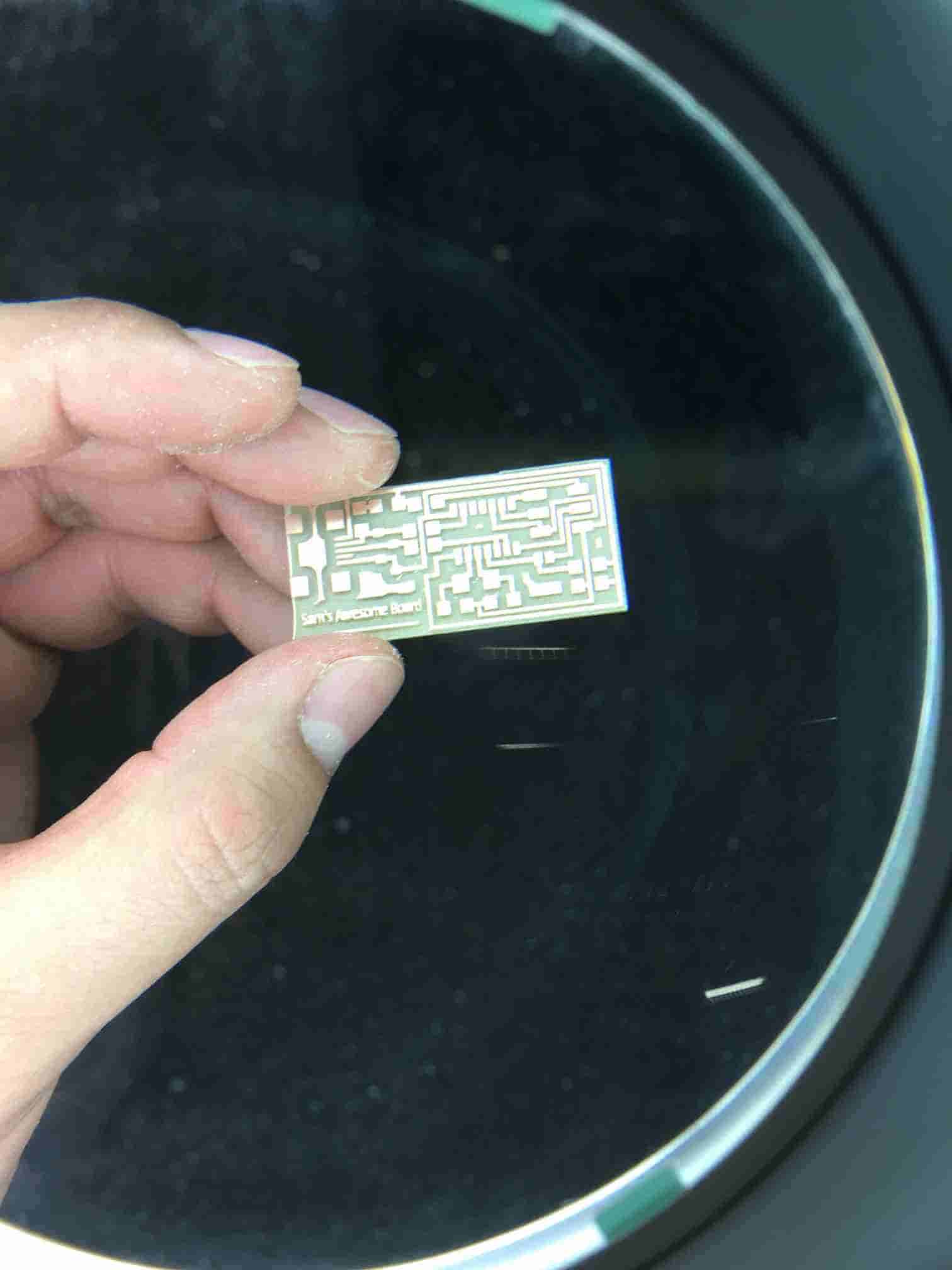
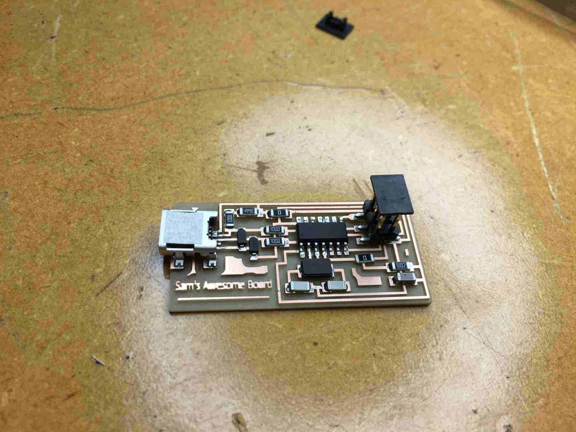
Once it was done milling out the board I was ready to load the outline.png, shown in Figure 3, to the program and this time using the 1/32 option. Once the right settings were set and the new bit was changed, I again clicked "send it!" and watched the mill cut that material up. After it cut out the board I was ready to start stuffing the board with its components following the diagram (Figure 4) as provided in the tutorial. Figure 5 shows the board ready for it to be stuffed with components. This was probably my least favorite part of this weekly assignment, stuffing the board. My hands and eyes really don't like dealing with little components and placing the solder paste was difficult with shaky hands. But I was able to get it done as shown in Figure 6. Now it was time to make sure the board was built right by programming it.
Using Ubuntu and following the tutorial, I first downloaded the correct files from the academy site. From here I changed the directory to this file and began the programming process. The following commands are what I used to program the board:
make clean
make hex
sudo make fuse
sudo make program
After each of these commands, I made sure that it was programming the board correctly. The last command of this programming assignment lets you check to make sure the board is recognized by the computer. After typing this command, the computer did not recognize my board. Sad face. This means I needed to troubleshoot my board in order to get it programmed right.
Figure 1: Image Used to Cut Out Board with 1/64" Bit
Figure 2: Board After traces.png Program was Done Running
Figure 3: Image Used to Cut Entire Board Out From Material with 1/32" Bit
Figure 4: Diagram Followed to Stuff Board with Compenents
Figure 5: Board Ready for Stuffing
Figure 6: Board Stuffed and Ready for Programming
Troubleshooting
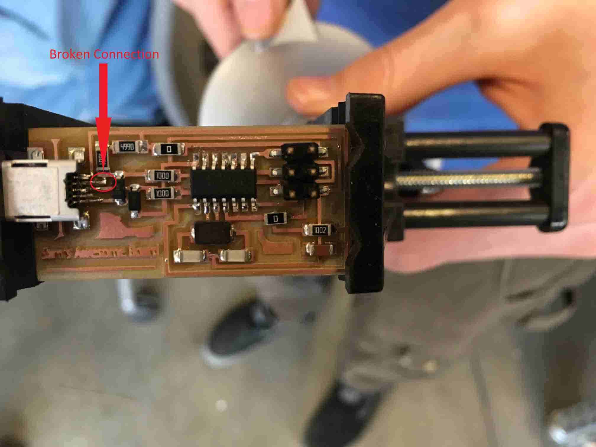
Since my board wasn't getting recognized by the computer, I knew there was a problem with it. The AVR held a green light when everything was plugged in, meaning it was reading the chip. So after talking with Kadin and Steven they thought the usb wasn't soldered correctly. After looking at it, we also noticed there was mostly likely a short also between the leads on the mini usb. Taking a razor blade I tried to carefully cut the shorts. I then ran through the programming process again, but it still wasn't getting recognized by the computer. After looking at the board again under a magnifying glass I noticed that one of the copper leads to the mini usb had actually broken as shown in Figure 7. From here I tried to solder the connection back together, but after running through the programming again it still didn't work. Since I had tried a good amount of troubleshooting on this board to have it not be working, I decided to build a completely new board.
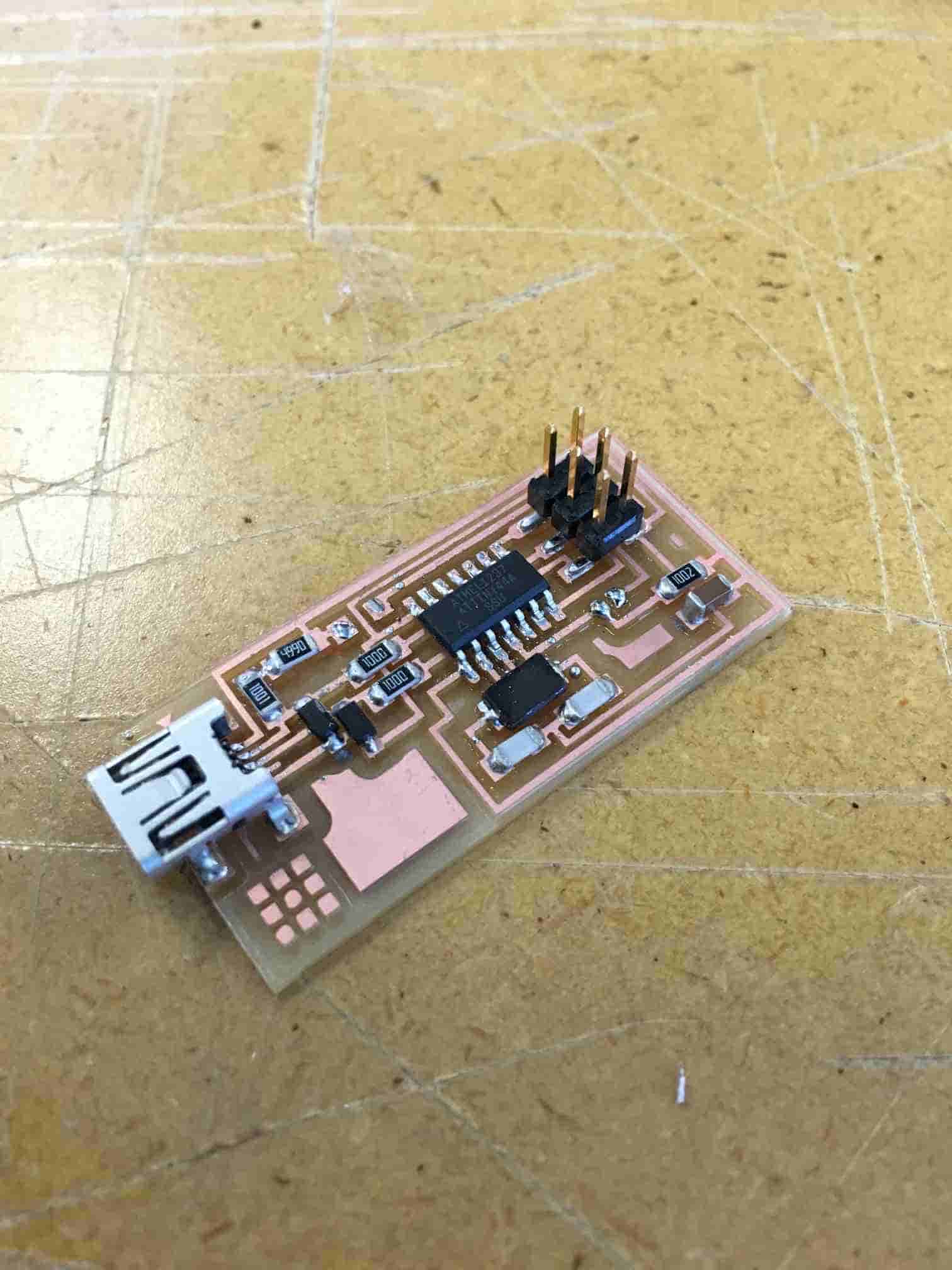
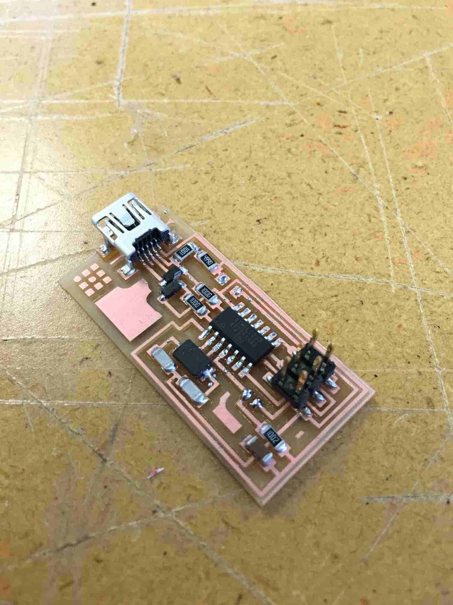
Following the same process, I milled out and stuffed a new board. Again, after running through the programming process the new board wasn't getting recognized by the computer. *@#&@! *$&@%! ^$^@%@!&#^@!&@*! You probably understand the words I am using here. Anyways, Steven Fett and I started to troubleshoot this new board. One of the things he noticed was that one of my diodes was reversed. Did this fix the problem? No. I then replaced the tiny44 chip. Fixed? No. Again examining the board I noticed the 20MHz crystal wasn't sealed down all the way, so I fixed that. Working? Still no luck. After this I applied more paste to the USB using a cotton swab to apply the paste. Finally after all of this troubleshooting and running through the programming, it was picked up by the computer! WOO! Figures 8 and 9 show my new working and finished board.
Text File Showing Board Recognized by Computer: Fab ISP Programming.txt
Figure 7: First Board with Broken Copper Connection
Figure 8: New Working Board
Figure 9: Awesome New Programmed Working Board
Lessons Learned
1) I really don't like building boards.
2) I REALLY don't like building boards.
3) Troubleshooting boards is a pain.
4) Patience